Wednesday, November 10, 2010

Air Temperature Sensor

ATS - ( Air temperature Sensor )
THA - ( Thermistor Air )
IAT - ( Intake Air Temperature )


Resistance and Temperature Graph


Does the sensor meet the manufactures specifications? Why or why not?

Yes it does meet the specification

What type of thermistor is this?

Air Temperature Sensor NTC.

What do you observe about your results of the air coolant sensors?

I oberved that as the temperature increases the resistance decreases.

Thermo Fan Switch

Thermo Fan Switch


Resistance and Temperature Graph


Does the fan switch meet the manufacturer's specifications? Why or why not?

Yes it does because my reading is correct according to the specification.

Is this a thermistor?

Yes it is a thermistor because it is NTC.

Explain the internal operation and why your resistance changes?

As your engine temperature increases or decreases the resistance changes giving connectivity to the relay which actuats thermo fan to work.

Coolant Temperature Sensor ( CTS )

CTS - Coolant Temperature Sensor.
THw - Thermistor water
ECT - Engine Coolant Temperature


Does the sensor meet the manufacturer's why or why not?
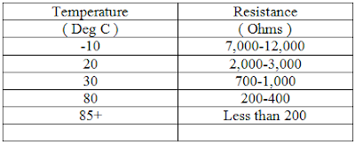
Yes, the resistance dos meet the manufacturer's specifications with the temperature change. Specifications are 2-3kilo ohms when it is cold and 200-400 ohms when it is hot.

What type of thermistor is this?

This is a water temperature sensor of toyota and it NTC.

Explain the internal operation of the sensor?

It measures engine coolant temperature which changes its resistance. If the resistance increases with coolant temperature then it is the PTC whereas if the resistance decreases with coolant temperature then it is NTC.

Vane or Flap Air Flow Sensor/Meter (AFM)

Checking sensor operation.

Vane type air flow meters:


Table for the vane angle and voltage out


Plot your results on thr graph


Are your results within the manufacturer's specifications, why or why not?

It is not because my graph does not look right.

Explain its internal operation and why your voltage changes.

The vane moves and allows the air flow into the engine. The vane is connected to the potentiometer which has variable resistor. The changes in voltage determines the amount of air flowing into the engine.


Air Flow /Mass Sensor ( MAF )

Air Flow / Mass Sensor (MAF)


What voltage did you get when you first powered up the sensor without passing air over the sensor?
1.802V

How did the voltage change when air was passed over the sensor?

The voltage changes depending on the amount of air being passed through the sensor.

Are your results within the manufactures's specifications, why or why not?

Yes it does match the manufactures specification.

Explain the internal operation of this sensor.

Air flow sensor measures the amount of air flowing into the inlet manifold. There are various types of air flow sensors namely for vane type, carmen vortex, hot wire type and MAP type. Each have different operations but same functions e.g MAP sensor works with the vacuum pressure inside the inlet manifold. The higher the vacuum the lower the manifold pressure and the lower the vacuum the higher the mnifold pressure. The changes in voltage is then picked up by the ECU which determines the injection amount.

Tuesday, November 9, 2010

Manifold Absolute Pressure ( MAP )

MAP - Manifold Absolute Pressure


Graph of the MAP


Does the MAP sensor match the manufactures specifications, why or why not?

Yes it does match the manufactures specifications because I have same voltage which is 3.2volt.

Does a MAP sensor read vacuum or pressure?

The MAP sensor reads the vacuum.

Explain the internal operation of this sensor and why the output voltage changes.


It measures the variation of the intake manifold pressure and output voltage changes because the signal is going to the ECU. The increase and decrease of the voltage indicates the pressure in the intake manifold depending on the vehicles manufacturers specifications.


Throttle Position Switch

Throttle Position Switch ( TPS)


What does throttle position switch do?

The throttle position switch detects throttle position at idle or full throttle by using switch contacts that are connected or disconnected as throttle position changes.

This type of switch can have two or three contact positions and is usually checked and adjusted using a multimeter.

Adjustment is made by loosening the mounting screws and rotating the switch assembly.

ON - OFF type throttle position switches can have:
Two position ( three pin ) or
Three position (four pin)

Testing the throttle position switch
The TPS signal is very important to ensure smooth and economic engine running and the TPS is made to be adjusted to ensure optimum operation.

The condition of the contacts inside the switch is the first test, and should be checked for high resistance in both the idle and full throttle position.


Place the ohm meter across the E and IDL pins and with the throttle shut, Check for continuity.

Place the ohm meter across the E and PSW pins and check for continuity when the throttle is wide open.

Note : PSW means power switch ( WOT )

IDL means idle circuit

E means earth

Plot your findings on the graph


Explain the internal operation of this sensor and why the resistance changes.

When the car is on idle the switch is normally closed and when the throttle butterfly turn "on" the switch then slowly transists to PWC after 20 degrees.