Saturday, November 13, 2010

Input Sensors and Actuators On - Vehicle

Make > Nissan

Model > Skyline

Year > 2000
1.0 Battery Voltage to Injectors

1.4 Record the voltage to the fuel injector

13.56V

Discuss why would we bother checking the voltage supply to the fuel injectors?
It is important to ensure that voltage is present at the injectors so that the engine can run efficiently. If there is no voltage, the injectors will not be activated therefore the vehicle will not start.

1.5 If we find lower voltage at the injectors than at the battery, what can that mean? And how would injector operation be affected?
  1. Bad connection
  2. Fault in the ECU
So injectors will not be able to work efficiently so the ECU will switch to limp mode.

1.6 Draw a full circuit diagram for the fuel injectors, including battery , ignition switch , main relay, and how the injectors are switched:

2.0 Reference Voltage at TPS sensor

2.4 Record the reading from the meter

5.14V

Is this acceptable or unacceptable reading?

This is a acceptable reading.


2.5 What is the purpose of the reference voltage to the throttle position sensor?

To supply the 5 volts input and to compare the signal wire with 5 volts.

2.6 What could cause problems so that there is not the correct refrence voltage at the throttle position sensor?

If the refrence voltage is incorrect the ECU will be getting the incorrect information about how far the throttle is opened.

3.0 Ground at TPS sensor

3.3 Record the voltage on the meter

0.05V

3.4 What does this voltage tell you about the ECU earth or ground? Why is it important to measure it?

Since there is no voltage drop therefore the ECU grounding is good.

3.5 Discuss what could go wrong so that the ECU earth or ground is not good.

  1. Broken wires
  2. Dry joints
  3. Corruded joints
  4. Loose wires
  5. Damaged circuit board.

4 Throttle Position Sensor return/output

4.2 Record the reading from the meter

5.18V

4.3 Open the throttle to about the half open position, ( make sure engine is not running ) and record the reading on the meter

2.288V

4.4 Open the throttle to the full open position, ( make sure engine is not running ) and record the reading on the meter.

4.05V

4.5 It is O.K

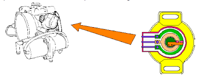
4.7 Describe how a TPS sensor works.

It acts like variable resistor to measure the opening angle of the throttle and idle circuit with the throttle butterfly fully closed, the idle cicuit activates and airflows into engine through the auxillery air values and with the throttle at half or full open the signal is sent to the ECU which determines the injection amount accordingly.

4.8 Discuss what type of sensor voltages should go to the ECU as the throttle is opened and closed.

With the throttle closed the voltage will be minimum whereas the throttle fully opened the voltage will be higher but less than 5 volts.

4.9 Describe problems which could occur to prevent the TPS from sending the correct voltage to the ECU.

  1. tempered with
  2. loose connectors
  3. faulty TPS

4.91 Draw a full circuit diagram for the TPS on this vehicle:


5.0 Throttle Position Switches

5.2 Record wire colours and voltages

  1. Idle wire colour: White / Blue stripe
  2. Volts at idle: 12.33V
  3. Volts at part throttle or open throttle : 2.2V
  4. Wide Open Throttle wire colour: Red / Blue stripe
  5. Volts at idle or part throttle: 2.3V
  6. Volts at open throttle: 4.02V

5.4 Why is this output needed for the ECU to properly run the engine? How do these outputs change how the engine runs in the different conditions of idle, part throttle cruise, and wide open throttle power?

The output from the TPS determines the opening angle and amount of air flowing into the engine. The ECU then determines the fuel injection amount with regards to the other input sensors. The wider the throttle opening angle the more air flow more injection amount.

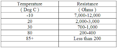
6.0 ECT Engine Coolant Temperature ) Sensor

6.3 Record the reading from the meter

1.8V

6.4 Is the engine cold, between cold and normal temperature ( warming up), or at normal operating temperature ?

Normal operating temperature

6.5 Does the voltage reading above seem right for the temperature of the engine? (yes or no)

Yes

6.6 Let the engine warm up for about two more minutes, and record the voltage of the ECT sensor now:

1.67V

6.7 A warmer engine should usually show a lower voltage. Is the reading above lower than the first reading ? ( yes or no )

Yes

6.8 Describe how an ECT sensor works.

According to the testing as the engine gets warmer the voltage decreases therefore it is negative temperature co-efficient (NTC)

6.9 Describe how the ECT sensor voltage affects the fuel injection output from the ECU.

Higher voltages will determine the engine is cold therefore the fuel injection amount will be more whereas the lower voltages of the ECT the ECU would senses that the engine is at normal operating temperature and hence the injection amount will decrease.

6.10 Describe what could go wrong to create an incorrect voltage for the ECU.

  1. Shorted out
  2. Bad connections
  3. Faulty ECT

6.11 Draw the circuit diagram for the ECT sensor


7.0 Ground Coolant Temperature Sensor

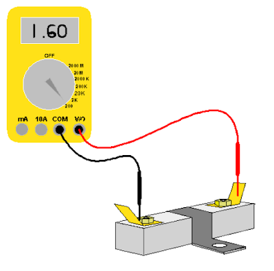
7.1 Record the voltage on the meter

0.04V

7.5 What does this voltage tell you about the ECU earth or ground? Why is it important to measure it?

It tells me that the ECU earth has good grounding therefore it is below the specification and the voltage is 0.04V without any voltage drop.

7.6 Discuss what could go wrong so that the ECU earth or ground is not good.

  1. Earth wire is loose or broken
  2. Corrude joint

4.0 RPM Sensor or Crank Position Sensor ( CKP )

4.5 Record the reading from the meter

1.86V

4.6 Increase engine RPM to about 2500 rpm. Record the reading from the meter.

0.683V

4.7 Return the engine to idle speed. Switch the voltmeter to read DC volts. Record the reading from the meter.

2.5V

4.8 Increase engine RPM toabout 2500 rpm. Record the reading from the meter.

2.401V

4.9 Switch the voltmeter to read Hz. Record the reading from the meter.

2.058KHz

4.10 Increase engine RPM to about 2500 rpm. Record the reading from the meter.

7.49KHz

4.11 Which setting best showed if the RPM sensor was working AC volts, DC volts or Hz

I think the best setting is showed by the Hz

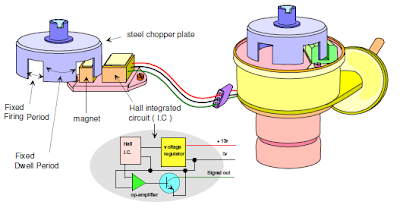
4.12 What type of RPM or Crank sensor is on your engine.

I have inductive sensor on my vehicle's engine

4.12 Describe how this type of RPM or Crank sensor works.

This sensors works by magnets and coils spinning on the CAM.

4.13 Discuss how using different functions of your meter can help you to accurately measure the sensor output when you don't have an oscilloscope available?

The meter gives you the accurate voltage and resistance.

4.14 What can go wrong so the ECU did not receive the correct signal from the RPM or Crank sensor.
  1. Faulty sensor
  2. Broken wire or loose connection

4.15 Draw the circuit diagram of RPM or Crank sensor.


5.0 MAP Sensor

5.6 Record the reading from the meter

5.01V

5.8 Record the reading from the meter

5.20V
5.9 Record the increased reading on the meter.

5.57V

5.10 Describe how the MAP sensor works to tell the engine how much air comes into the engine?

The signal is sent by vacuum pressure on the manifold that is the higher the vacuum pressure the lower the manifold pressure or the higher the manifold pressure the lower the vacuum pressure.

5.11 Describe how the readings above are correct or incorrect for this engine
The readings above are correct because at the ignition on the voltage is 5.01V and at the idle the voltage increases to 5.20V and when you accelerate for short while it increases to 5.57V.

5.12 What could go wrong so the ECU did not receive the correct signal from the MAP sensor?
  1. Faulty MAP sensor
  2. Broken or loose connection
5.13 Draw the circuit diagram for the MAP sensor


MAF Sensor
5.18 Record the reading from the meter
0.22V

5.20 Record the reading form the meter

1.4V

5.21 Record the increased reading on the meter

2.2V
5.22 Describe how the MAF sensor works to tell the ECU how much air came into the engine. Include what readings might be normal under different load conditions.
It works according to the higher and lower voltage therefore amount of airflow into the engine whereas when the voltage is higher the greater amount airflow enters into the engine.

5.23 Discuss how the MAF reading above are correct incorrect for this engine.

The readings above is correct because the voltage varies when it is at ignition, the voltage is 0.22V and when it is at idle than the voltage increases to 1.4V and when you accelerate for short while than it increases to 2.2V.

5.24 What could go wrong so the ECU did not receive the correct signal from the MAF sensor?
  1. Fault in the MAF sensor
  2. Broken or loose connection.
9.0 IAT ( Intake Air Temperature), ACT ( Air Change Temperature ), or MAT ( Manifold Air temperature Sensor

9.4 Record the reading from the meter

1.87V
9.5 Is the reading more or less than the reading you had for the ECT?

More
Does this show the IAT sensor is colder or hotter than the ECT sensor?

Colder

9.6 Describe how the IAT sensor works.

It measures the amount of airflowing into the engine with the variation in the voltage which is sent to the amount of airflow.
9.7 Describe how the IAT reading affects the ECU outputs for the fuel injection. Include how an incorrect input could affect the fuel injection and engine running.

The differences with the voltage or variations determines the temperature of airflowing into the engine and the signal is sent to the ECU which determines the injection amount weather the engine is running cold or normal temperature.

9.8 Describe how the IAT sensor signal should change for different air temperature conditions

Difference at the voltages at the IAT sensor determines the amount of airflowing into the engine and hence the injection amount is determined by the ECU.

9.9 Describe what could go wrong to create an incorrect IAT signal for the ECU.

  1. fault in the IAT
  2. Broken or loose connection

9.10 Draw the wiring diagram for IAT sensor


10.0 Camshaft Position Sensor ( CMP )

10.3 Record your meter readings below in the different settings, and discuss which settings show the CMP is good .

DC Volts = 5.15V

AC Volts = 10.5V

Hz = 36.99KHz

% Duty Cycle = 22.1%

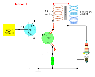
10.4 Draw the circuit diagram for Cam Position Sensor


Wiring up Ignition Systems

Wire up an ignition module using a function generator to trigger the module. Have a coil and a spark plug in the circuit so the spark plug can fire. Check with your tutor that you have done it correctly.


Wire up an ignition module using a distributor to trigger the module.
Have a coil and spark plug in the circuit so the spark plug can fire
Check with your tutor that you have done it correctly.


Wire up the wasted spark ignition system using the function generator to trigger the modules.
Have the coils and sparks plug in the circuit so the spark plugs can fire.
Check with your tutor that you have done it correctly.


Wire up the coil over ignition system using the function generator to trigger the module
Have the coil and spark plug in the circuit so the spark plug can fire
Check with your tutor that have done it correctly


Build a simplified ignition module

Find the maximum current value of the transistor from the data sheet, the resistance of the coil. Then calculate the resistor need to protect the circuit.

14V , 100mA

14/0.100 = 140 ohms

Connect your circuit up to the function generator and fire the spark plug.


What difficulties did you encounter in building this circuit?
The resistor prevented our circuit from working because the resistor was drawing too much current.

If you were going to build this circuit again what would you do differently?
I will not involve the resistor.

Friday, November 12, 2010

Testing Ignition Coil

Iginition Coil Primary and Secondary


Coil Specifications


Coil # 1 No: Lucas 16c6

Coil # 1 Voltage: 6V

Coil # 1 Primary: 1.43 - 1.58 ohms

Coil # 1 Secondary: 7.5 kilo ohms


Coil # 2 No: Diamond F - 088

Coil # 2 Voltage: 12V

Coil # 2 Primary: 0.72 - 0.88 ohms

Coil #2 Secondary: 10.89 -13.3 kilo ohms


Coil Test Results

Coil # 1 Primary: 1.3 ohms

Coil # 1 Secondary: 7.74 kilo ohms

Coil # 1 Earth leakage Test: OL


Coil # 2 Primary: 0.7 ohms

Coil # 2 Secondary: 12.9 kilo ohms

Coil # 2 Earth Leakage Test: OL


Serviceable Coil # 1: Yes

Serviceable Coil # 2: Yes

Wasted Spark Coil Pack

Coil # 1 Secondary: 12.5 kilo ohms

Coil # 2 Secondary: 12.53 kilo ohms

Coil # 3 Secondary: 12.67 kilo ohms


Coil # 1 Primary: 0.7 ohms

Coil # 2 Primary: 0.8 ohms

Coil # 3 Primary: 0.7 ohms


Testing Ballast Resistors

Specifications

Ballast resistor 1 No: BR1

Ballast resistor No 1 ohm spec: 2 ohms

Measured Resistance Values

Ballast Resistor No 1 Measured Ohms: 2 ohms

Serviceable? Yes


Measuring Current Draw and Voltage Drop

Current Draw : 3.39A

Coil calculated Voltage Drop : 1.3 x 3.39 = 4.407

Coil measured Voltage drop : 4.77V

Ballast resistor calculated voltage drop : 2 ohms x 3.39 = 6.78V

Ballast resistor measured voltage drop: 4.9V


Did your calculated values equal your measured results explain why or why not?

Yes it does equalswith measured results, although the second time I checked the resistance of the ballast the resistor I got was much less resistance ( 1.67 ohms ) because the first time I checked it the resistor was much hotter which increased the resistance.

Thursday, November 11, 2010

Optical Distributor

Optical Distributor

Red - 12v
Black - Earth
Blue - signal out


Draw the waveform


Describe the waveform using arrows and A,B,C etc. What is happening at different points?
On the waveform when the optical distributor begins the next on of the four blade on the ( Chopper Plate ) will interrupt the signal in the photo electric shell, switching it off. This switching happens faster as the car is under higher load driving conditions.

Explain the difference between Hall - Effect, optical and inductive signals

Hall - Effect uses a steel chopper plate whereas optical uses infra red diodes and inductive signals with reference mark on the rotational crank pulley

In each of the speed sensor above, how does the degrees turned relate to the degrees of crank shaft rotation?

It is done by the reference mark and graduction on the crank pulley.

Injector Testing

Checking injectors off a vehicle.
Only two injectors were available.


Checking injectors for audible "click"


State any other engine problems that could give the same result as an injector not firing.

  1. Nozzle could be blocked

  2. Fuel line could have been cut to an injector.

Cheaning Injectors Off a Vehicle

When removing fuel injectors from the engine take care to be sure that the vehicle is turned off and handle the nozzle with care to avoid any damage.

What are the manufacturer's specifications in relation to :

Injector leakage: no drip therfore 0 drips per minute.

Injector Flow Rate: 45cc per minute flow rate


Test Results

How many injectors require attention?

Injector 4

Describe the condition of all the injectors that you tested.

All the injectors were new and working only injector number 4 had a problem with the faulty connection.

Hall - Effect Sensor

Hall - Effect Sensor


Note : Always use 5 volts reference unless instructed otherwise.

Hall - Effect Distributor


Wednesday, November 10, 2010

Oxygen Sensor

Speed or Position Sensor

> Inductive sensor
> Magnetic reluctor sensor


Note : cold is from -10 degree cellius - 50 degree cellius

Checking Air Gap using feeler guage, and measuring air gap between the piclup coil projection and the reluctor tip.

Adjusting Reluctor Air Gap on Magnetic Distributor

Note : Only brass feeler guage to be used.


Adjusting the Reluctor Air Gap


Formula: Probe x volts / div x number of squares and increments

Describe the waveform using arrows and A,B,C etc. What is happening at different points?

At the point A the magnetic field is collapsing

At the point B the reluctor tip has reached it's maximum distance away from the magnet.

At the point C it shows the voltage increasing due to the reluctor getting closer to the magnet.

At the point D the magnetic field collapsing again and repeating the whole process.

Knock Sensor

Knock Sensor

Waveform on oscilloscope


Explain why we are reading a voltage from this sensor when we are not supplying a voltage to it?
It is because the knock sensor is the passive component.


Air Temperature Sensor

ATS - ( Air temperature Sensor )
THA - ( Thermistor Air )
IAT - ( Intake Air Temperature )


Resistance and Temperature Graph


Does the sensor meet the manufactures specifications? Why or why not?

Yes it does meet the specification

What type of thermistor is this?

Air Temperature Sensor NTC.

What do you observe about your results of the air coolant sensors?

I oberved that as the temperature increases the resistance decreases.

Thermo Fan Switch

Thermo Fan Switch


Resistance and Temperature Graph


Does the fan switch meet the manufacturer's specifications? Why or why not?

Yes it does because my reading is correct according to the specification.

Is this a thermistor?

Yes it is a thermistor because it is NTC.

Explain the internal operation and why your resistance changes?

As your engine temperature increases or decreases the resistance changes giving connectivity to the relay which actuats thermo fan to work.

Coolant Temperature Sensor ( CTS )

CTS - Coolant Temperature Sensor.
THw - Thermistor water
ECT - Engine Coolant Temperature


Does the sensor meet the manufacturer's why or why not?
Yes, the resistance dos meet the manufacturer's specifications with the temperature change. Specifications are 2-3kilo ohms when it is cold and 200-400 ohms when it is hot.

What type of thermistor is this?

This is a water temperature sensor of toyota and it NTC.

Explain the internal operation of the sensor?

It measures engine coolant temperature which changes its resistance. If the resistance increases with coolant temperature then it is the PTC whereas if the resistance decreases with coolant temperature then it is NTC.

Vane or Flap Air Flow Sensor/Meter (AFM)

Checking sensor operation.

Vane type air flow meters:


Table for the vane angle and voltage out


Plot your results on thr graph


Are your results within the manufacturer's specifications, why or why not?

It is not because my graph does not look right.

Explain its internal operation and why your voltage changes.

The vane moves and allows the air flow into the engine. The vane is connected to the potentiometer which has variable resistor. The changes in voltage determines the amount of air flowing into the engine.


Air Flow /Mass Sensor ( MAF )

Air Flow / Mass Sensor (MAF)


What voltage did you get when you first powered up the sensor without passing air over the sensor?
1.802V

How did the voltage change when air was passed over the sensor?

The voltage changes depending on the amount of air being passed through the sensor.

Are your results within the manufactures's specifications, why or why not?

Yes it does match the manufactures specification.

Explain the internal operation of this sensor.

Air flow sensor measures the amount of air flowing into the inlet manifold. There are various types of air flow sensors namely for vane type, carmen vortex, hot wire type and MAP type. Each have different operations but same functions e.g MAP sensor works with the vacuum pressure inside the inlet manifold. The higher the vacuum the lower the manifold pressure and the lower the vacuum the higher the mnifold pressure. The changes in voltage is then picked up by the ECU which determines the injection amount.

Tuesday, November 9, 2010

Manifold Absolute Pressure ( MAP )

MAP - Manifold Absolute Pressure


Graph of the MAP


Does the MAP sensor match the manufactures specifications, why or why not?

Yes it does match the manufactures specifications because I have same voltage which is 3.2volt.

Does a MAP sensor read vacuum or pressure?

The MAP sensor reads the vacuum.

Explain the internal operation of this sensor and why the output voltage changes.


It measures the variation of the intake manifold pressure and output voltage changes because the signal is going to the ECU. The increase and decrease of the voltage indicates the pressure in the intake manifold depending on the vehicles manufacturers specifications.


Throttle Position Switch

Throttle Position Switch ( TPS)


What does throttle position switch do?

The throttle position switch detects throttle position at idle or full throttle by using switch contacts that are connected or disconnected as throttle position changes.

This type of switch can have two or three contact positions and is usually checked and adjusted using a multimeter.

Adjustment is made by loosening the mounting screws and rotating the switch assembly.

ON - OFF type throttle position switches can have:
Two position ( three pin ) or
Three position (four pin)

Testing the throttle position switch
The TPS signal is very important to ensure smooth and economic engine running and the TPS is made to be adjusted to ensure optimum operation.

The condition of the contacts inside the switch is the first test, and should be checked for high resistance in both the idle and full throttle position.


Place the ohm meter across the E and IDL pins and with the throttle shut, Check for continuity.

Place the ohm meter across the E and PSW pins and check for continuity when the throttle is wide open.

Note : PSW means power switch ( WOT )

IDL means idle circuit

E means earth

Plot your findings on the graph


Explain the internal operation of this sensor and why the resistance changes.

When the car is on idle the switch is normally closed and when the throttle butterfly turn "on" the switch then slowly transists to PWC after 20 degrees.

Monday, November 8, 2010

Engine Electronic Control Systems ( 4826 )

Sensors

TPS - Throttle Position Sensor

What does TPS do?
The purpose of the TPS is to monitor the position of the throttle in an engine combustion.

Potentiometer Type Sensors - are composed of variable resistors that have a slide contact, which changes its position as the throttle butterfly moves.
A voltage is supplied to the sensor by the E.C.U. As the throttle position changes, the output voltage from the sensor changes, this in turn is recognised and a comparision made by the E.C.U to its memory. These sensors are adjusted by loosening the sensor mounting screws.


Checking the Throttle Position Sensor

What type of TPS is this?
It is a potentiometer type sensor.


Explain its internal operation and why your voltage changes.
The internal operation of the TPS is to monitor the position of the throttle in an engine combustion and the voltage changes because the potentiometer changes the resistance which results to change in voltage.

Now connect a power supply to your sensor and test the voltage output at different throttle angles.
Note: Always use 5V supply.


Now plot your findings on the Graph